Working with Subcircuits
Subcircuits are used to bring more clarity into a schematic. This is very useful in large circuits or in circuits, in which a component block appears several times.
In Qucs, each schematic containing a subcircuit port is a subcircuit. You can get a subcircuit port by using the toolbar, the components listview (in lumped components) or the menu (Insert->Insert port). After placing all subcircuit ports (two for example) you need to save the schematic (e.g. CTRL-S). By taking a look into the content listview (figure 1) you see that now there is a “2-port” right beside the schematic name (column “Note”). This note marks all documents which are subcircuits. Now change to a schematic where you want to use the subcircuit. Then press on the subcircuit name (content listview). By entering the document area again, you see that you now can place the subcirciut into the main circuit. Do so and complete the schematic. You can now perform a simulation. The result is the same as if all the components of the subcircuit are placed into the circuit directly.
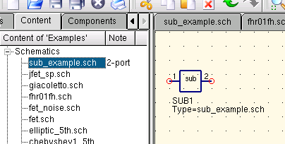
Figure 1 - Accesing a subcircuit
If you select a subcircuit component (click on its symbol in the schematic) you can step into the subcircuit schematic by pressing CTRL-I (of course, this function is also reachable via toolbar and via menu). You can step back by pressing CTRL-H.
If you do not like the component symbol of a subcircuit, you can draw your own symbol and put the component text at your favourite position. Just make the subcircuit schematic the current and go to the menu: File->Edit Circuit Symbol. If you have not yet drawn a symbol for this circuit. A simple symbol is created automatically. You now can edit this symbol by painting lines and arcs. After finished, save it. Now place it on another schematic, and you have a new symbol.
Just like all other components, subcircuits can have parameters. To create your own parameters, go back to the editor where you edited the subcircuit symbol and double-click on the subcircuit parameter text (SUB1 in the Figure 1). A dialog apperas and you now can fill in parameterswith default values and descriptions. When you are ready, close the dialog and save the subcircuit. In every schematic where the subcircuit is placed, it owns the new parameters which can be edited as in all other components.
Subcircuits with Parameters
A simple example using subcircuits with parameters and equations is provided here.
Create a subcircuit:
- Create a new project
- New schematic (for subcircuit)
- Add a resistor, inductor, and capacitor, wire them in series, add two ports
- Save the subcircuit as RLC.sch
- Give value of resistor as ‘R1’
- Add equation ‘ind = L1’,
- Give value of inductor as ‘ind’
- Give value of capacitor as ‘C1’
- Save
- File > Edit Circuit Symbol
- Double click on the ‘SUB File=name’ tag under the rectangular box
- Add name = R1, default value = 1
- Add name = L1, default value = 1
- Add name = C1, default value = 1
- OK
Insert subcircuit and define parameters:
- New schematic (for testbench)
- Save Test_RLC.sch
- Project Contents > pick and place the above RLC subcircuit
- Add AC voltage source (V1) and ground
- Add AC simulation, from 140Hz to 180Hz, 201 points
- Set on the subcircuit symbol
- R1=1
- L1=100e-3
- C1=10e-6
- Simulate
- Add a Cartesian diagram, plot V1.i
- The result should be the resonance of the RLC circuit.
- The parameters of the RLC subcircuit can be changed on the top schematic.