Getting Started with Analog Simulations
Qucs (speak: kju:ks) is a circuit simulator with graphical user interface. It is able to perform many different kinds of simulation (e.g. DC, s parameter). This document should give you a short description on how to use Qucs.
When you start Qucs the first time, it creates the directory ”.qucs” within your home directory. Every file is saved into this directory or into one of its subdirectories. After Qucs has been loaded, one sees the main window looking simular like the one in figure 1. On the right side, there is the working area (6) containing the schematics, data displays and so on. Using the tabular bar (5) above this area, you can quickly switch to every document currently open. On the left side of the Qucs main window, there is another area (1), whose content depend on the status of the above-lying tabular bar: “Projects” (2), “Content” (3) and “Components” (4). After running Qucs, the “Projects” (2) tab is activated. As it is the first time you started this program, the area is empty because you haven’t yet any project. Press the “New” button right above the area (1) and a dialog opens. Enter the name for your first project, e.g. “firstProject” and press the “Ok” button. Qucs creates a project directory into the ~/.qucs directory, for this example “firstProject_prj”. Every file belonging to this new project will be saved within this directory. The new project is immediately opened (as can be read on the window title bar) and the tabular bar is switched to “Content” (3), where the content of the currently opened project is displayed. You do not yet have any document, so press save button on the toolbar (or use the main menu: File->Save) in order to save the untitled document that still fills the working area (6). You will be ask for the name of your new document. Enter “firstSchematic” and press the “Ok” button.
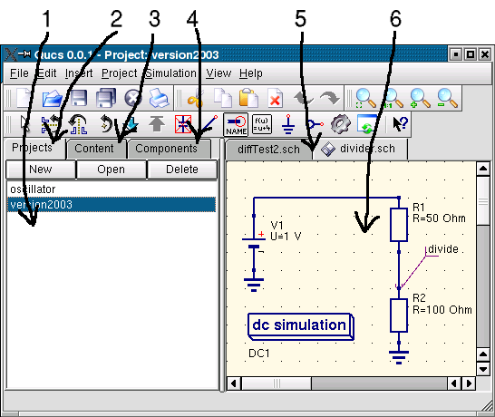
Figure 1 - Qucs main window
Now we want to make a simple DC simulation, i.e. we want to analyse the circuit in figure (1). Activate the “Components” tab ( (4) in figure 1). There, you see a combo box where you can choose a component group and, below, the components of the chosen component group. Choose “lumped components” and click on the first symbol: “Resistor”. Moving the mouse cursor into the working area (6) you are carrying a drawing of a resistor symbol. Pressing the right mouse button rotates the symbol, pressing the left mouse button places the component onto the schematic. Repeat this process for all components shown in figure 1. The voltage source can be found in the “sources” component class, the ground symbol can be taken from “lumped components” class or from the toolbar, the wanted simulation is defined by the big simulation blocks found in the “simulations” component class. To edit the parameters of the second resistor, double-click on it. A dialog opens where you can change the resistance. Enter “100 Ohm” into the edit field on the right side and press enter.
To connect the components, press the wire toolbar button (or use the main menu: Insert->Wire). Move the cursor onto an open port (marked by the small red circles). Clicking on it starts the wire. Now move to the end point and click again. The components are now connected. If you want to change the corner direction of the wire, click on the right mouse button before setting the end point. You can also end a wire without pressing on an open port or on a wire: Just double-click the left mouse button.
Last but not least, you must label the node where you want Qucs to caculate the voltage. Press on the label toolbar button (or use the menu: Insert->Wire Label). Now click on the chosen wire. A dialog opens and you can enter the node name. Type “divide” and click the “Ok” button. Now the circuit should look like the one in figure 1.
To start the simulation press the simulate toolbar button (or use the menu: Simulation->Simulate). A window opens and shows the progress. After finishing the simulation successfully, the data display is opened. Normally, all this happens so fast that you only see a short flickering. Now you have to place a diagram to see the simulation results. On the left side the “diagrams” component class has already chosen automatically. Press on the “Tabular” item, move to the working area and place it by clicking the left mouse button. A dialog opens where you can choose what should be displayed by the new diagram. In the left area you see the node name you have defined: “divide”. Double-click on it and it will be transfered to the right area. Leave the dialog by clicking the “Ok” button. Now you see the simulation result: 0.666667 volts. Wonderful, give yourself a clap on the shoulder!