Getting Started with Digital Simulations
Qucs is also a graphical user interface for performing digital simulations. This document should give you a short description on how to use it.
For digital simulations Qucs uses the FreeHDL program (http://www.freehdl.seul.org). So the FreeHDL package as well as the GNU C++ compiler must be installed on the computer.
There is no big difference in running an analog or a digital simulation. So having read the Getting Started for analog simulations, it is now easy to get a digital simulation work. Let us compute the truth table of a simple logical AND cell. Select the digital components in the combobox of the components tab on the left-hand side and build the circuit shown in figure 1. The digital simulation block can be found among the other simulation blocks.
The digital sources S1 and S2 are the inputs, the node labeled as Output is the output. After performing the simulation, the data display page opens. Place the diagram truth table on it and insert the variable Output. Now the truth table of a two-port AND cell is shown. Congratulation, the first digital simulation is done!
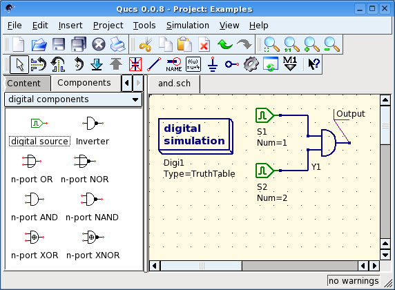
Figure 1 - Qucs main window
A truth table is not the only digital simulation that Qucs can perform. It is also possible to apply an arbitrary signal to a circuit and see the output signal in a timing diagram. To do so, the parameter Type of the simulation block must be changed to TimeList and the duration of the simulation must be entered in the next parameter. The digital sources have now a different meaning: They can output an arbitrary bit sequence by defining the first bit (low or high) and a list that sets the times until the next change of state. Note that this list repeats itself after its end. So, to create a 1GHz clock with pulse ratio 1:1, the list writes: 0.5ns; 0.5ns
To display the result of this simulation type, there is the diagram timing diagram. Here, the result of all output nodes can be shown row by row in one diagram. So, let’s have fun...
VHDL File Component
More complex and more universal simulations can be performed using the component “VHDL file”. This component can be picked up from the component list view (section “digital components”). Nevertheless the recommended usage is the following: The VHDL file should be a member of the project. Then go to the content list view and click on the file name. After entering the schematic area, the VHDL component can be placed.
The last entity block in the VHDL file defines the interface, that is, all input and output ports must be declared here. These ports are also shown by the schematic symbol and can be connected to the rest of the circuit. During simulation the source code of the VHDL file is placed into the top-level VHDL file. This must be considered as it causes some limitations. For example, the entity names within the VHDL file must differ from names already given to subcircuits. (After a simulation, the complete source code can be seen by pressing F6. Use it to get a feeling for this procedure.)