Trabajar con Subcircuitos
Los Subcircuitos se usan para dar más claridad a un esquema. Es muy útil en circuitos muy grandes o en circuitos en los que aparece un mismo bloque de componentes varias veces.
En Qucs cada esquema que contenga una conexión de subcircuito es un subcircuito. Para conseguir una conexión de subcircuitos use la barra de herramientas, la vista de componentes (en componentes sueltos) o el menú (Insertar -> Insertar conexión). Después de colocar todas las conexiones del subcircuito (por ejemplo, dos) tiene que guardar el esquema (pulse CTRL-S). Si echa un vistazo a la lista de contenidos (figura 1) verá que ahora aparecerá un “2-port” a la derecha del nombre del esquema (columna “Nota”). Esta nota marca todos los documentos que son subcircuitos. Ahora cmbie a un esquema en el que quiera usar el subcircuito. Después pulse en el nombre del subcircuito (vista de contenido). Volviendo a entrar en el área del documento verá que ahora puede colocar el subcircuito dentro del circuito principal. Hágalo y complete el esquema. Ahora puede realizar una simulación. El resultado es el mismo que si todos los componentes del subcircuito se hubieran colocado directamente en el circuito.
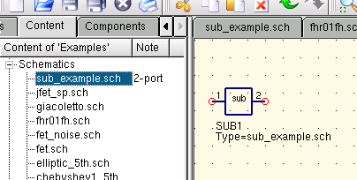
Figura 1 - Acceder a un subcircuito
Si selecciona un componente subcircuito (clic en su símbolo en el esquema) puede entrar en el esquema del subcircuito pulsando CTRL-I (por supuesto, esta función está accesible también via barra de herramientas y menú). Puede salir del subcircuito pulsando CTRL-H.
Si no le gusta el símbolo dado al componente de un subcircuito, puede dibujar su propio símbolo. Simplemente haga el esquema del subcircuito y vaya al menú: Archivo ->Editar símbolo de circuito. Si no ha dibujado aún un símbolo para este circuito se creará un dibujo simple para este. Ahora puede editar este símbolo pintando líneas y arcos. Cuando termine guárdelo. Ahora colóquelo en otro esquema y, voilá, tiene un nuevo símbolo.
Just like all other components, subcircuits can have parameters. To create your own parameters, go back to the editor where you edited the subcircuit symbol and double-click on the subcircuit parameter text (SUB1 in the Figure 1). A dialog apperas and you now can fill in parameterswith default values and descriptions. When you are ready, close the dialog and save the subcircuit. In every schematic where the subcircuit is placed, it owns the new parameters which can be edited as in all other components.
Subcircuits with Parameters
A simple example using subcircuits with parameters and equations is provided here.
Create a subcircuit:
- Create a new project
- New schematic (for subcircuit)
- Add a resistor, inductor, and capacitor, wire them in series, add two ports
- Save the subcircuit as RLC.sch
- Give value of resistor as ‘R1’
- Add equation ‘ind = L1’,
- Give value of inductor as ‘ind’
- Give value of capacitor as ‘C1’
- Save
- File > Edit Circuit Symbol
- Double click on the ‘SUB File=name’ tag under the rectangular box
- Add name = R1, default value = 1
- Add name = L1, default value = 1
- Add name = C1, default value = 1
- Aceptar
Insert subcircuit and define parameters:
- New schematic (for testbench)
- Save Test_RLC.sch
- Project Contents > pick and place the above RLC subcircuit
- Add AC voltage source (V1) and ground
- Add AC simulation, from 140Hz to 180Hz, 201 points
- Set on the subcircuit symbol
- R1=1
- L1=100e-3
- C1=10e-6
- Simular
- Add a Cartesian diagram, plot V1.i
- The result should be the resonance of the RLC circuit.
- The parameters of the RLC subcircuit can be changed on the top schematic.