Chapter 7. Qucs and SPICE simulation models that work with ngspice, Xyce and SPICE OPUS
7.1 Introduction
For a circuit simulator to be a useful circuit design aid it must be able to simulate a range of analogue and digital circuits which include passive components, semiconductor devices, integrated circuits and non-electrical devices when needed. By combining Qucs with ngspice and Xyce the number of available simulation models has increased significantly, making the spice4qucs version of Qucs more flexible and powerful, when compared to earlier Qucs releases. One of the primary motives behind the development of spice4qucs was to provide Qucs users with access to published SPICE component models while keeping all the existing Qucs models and simulation capabilities unchanged. With the first release of spice4qucs, as Qucs-0.0.19S, this aim has largely been achieved. However, there are still significant gaps in the Qucs-0.0.19S simulation capabilities (for example no SPICE 3f5 .PZ simulation yet) and model coverage (for example the number of power analogue and digital models are limited). More work is planned on model development for later releases of the software, including improvements to power device models and the introduction of XSPICE digital models for true mixed-mode analogue-digital simulation. Any improvements and additions to the Qucs-0.0.19S model complement will be recorded in this document as they are introduced by the Qucs Development Team.
This chapter of the spice4qucs-help document consists of two parts; firstly a brief component specification and a more detailed technical reference, and secondly a selection of typical simulation examples which illustrate the use of the various component models. Part two has been added as an aid to help Qucs users appreciate the new style software and the differences between Qucs-0.0.19S and earlier releases of Qucs.
No two circuit simulators are equipped with an identical number, and the same identical types, of circuit simulation models. This is even true with the various implementations of SPICE developed from SPICE 3f5. Hence, by combining Qucs, ngspice and Xyce within one circuit simulation software package there has to be a way of identifying which models work with which simulator. A second feature that further complicates model selection is the fact that supposedly identical models representing the same generic device, for example a BJT, may be based on different physical device equations and a different number of device parameters. In an attempt to identify which model works with which simulator the Qucs Development Team have adopted the following model symbol colouring scheme; existing Qucs models are coloured dark blue (no change), SPICE models which work with both ngspice and Xyce are coloured red, SPICE models that only work with ngspice are coloured cyan and SPICE models that only work with Xyce are coloured dark green. This scheme is not perfect because a number of the original Qucs models also work with ngspice and Xyce. However, for legacy reasons the Qucs Development Team has decided not to change the colours of these models at this time. This decision will probably be reviewed in later releases of Qucs.
The models shown in Figure 7.1 are the original Qucs-0.18 models which can be included in ngspice and Xyce simulations. Please NOTE that for those Qucs users who do not wish to simulate circuits with either ngspice or Xyce all the models distributed with Qucs-0.0.18 work with Qucs-0.0.19S without any modification via the usual Simulation (key F2) command. So far no attempt has been made to interface Qucs Verilog-A models with ngspice or Xyce. This task is scheduled for a later spice4qucs development phase.
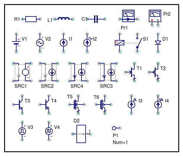
Figure 7.1. Qucs-0.0.18 models that work with ngspice and (sometimes) Xyce.
7.2 Spice4qucs component specifications and technical reference
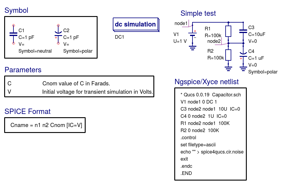
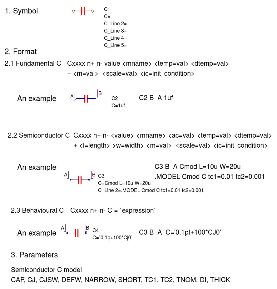
Capacitor (C)
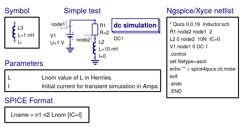
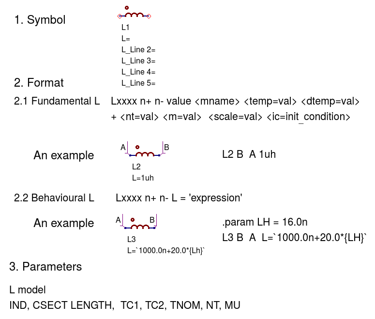
Inductor (L)
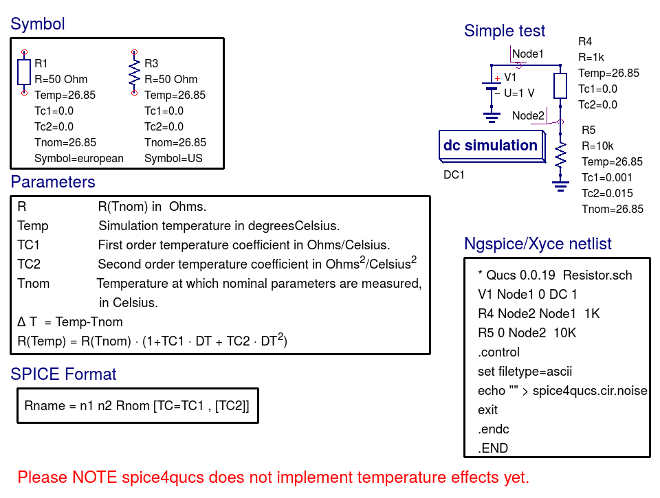
Resistor (R)
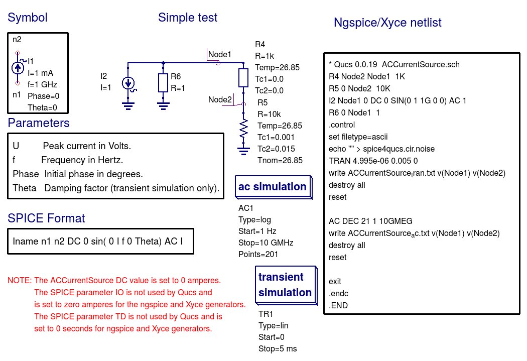
Independent AC Current Source (I)
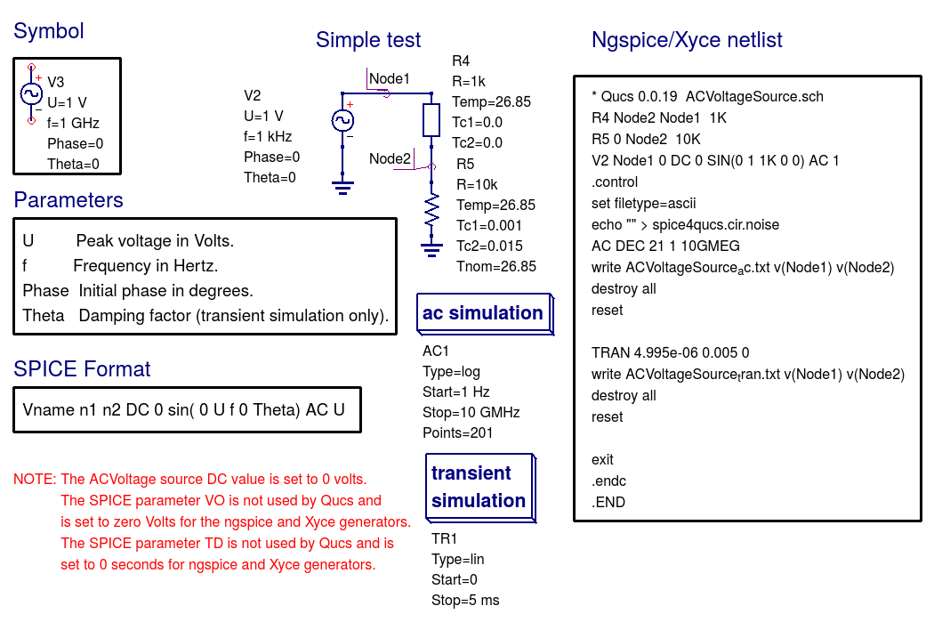
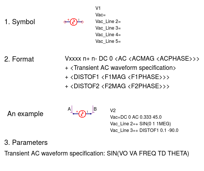
Independent AC Voltage Source (V)
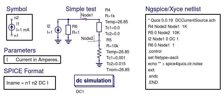
Independent DC Current Source (I)
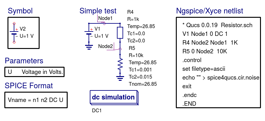
Independent DC Voltage Source (V)
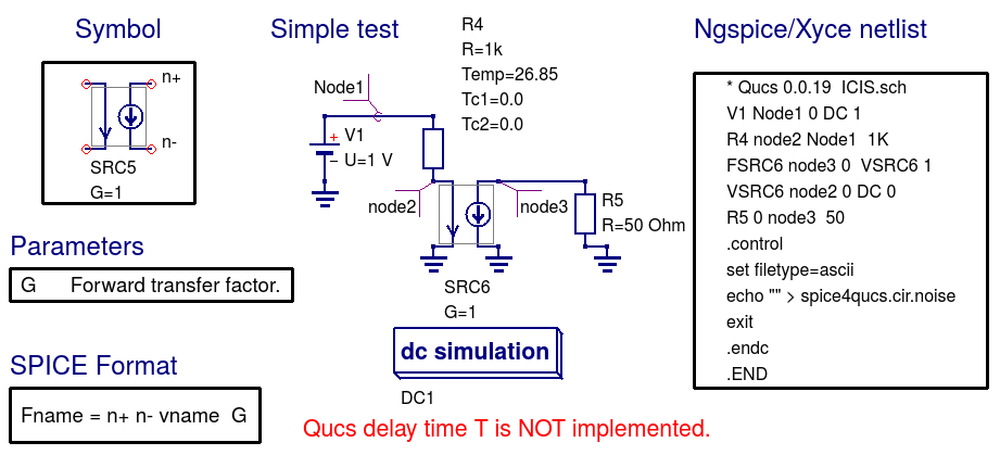
Linear Current Controlled Current Source (F)
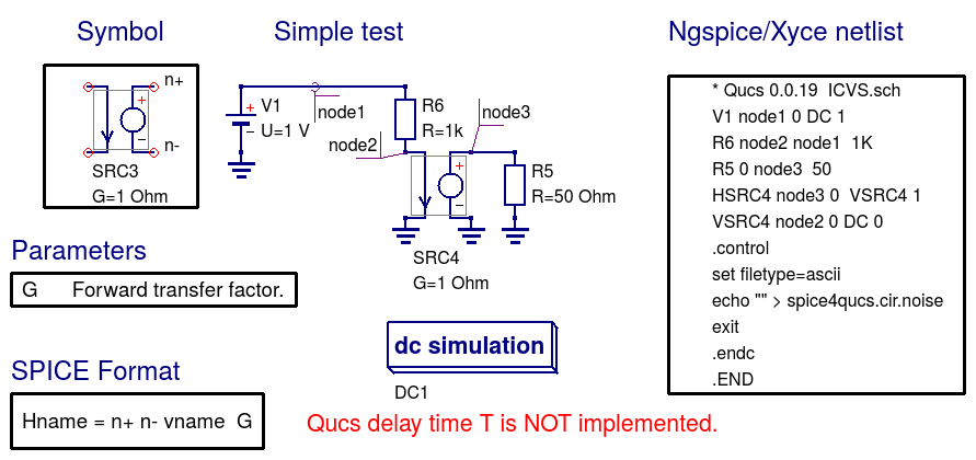
Linear Current Controlled Voltage Source (H)
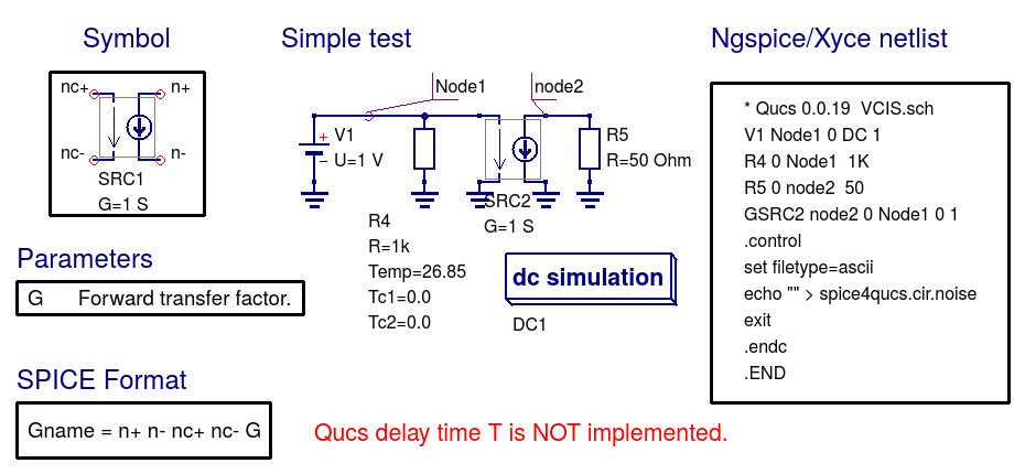
Linear Voltage Controlled Current Source (G)
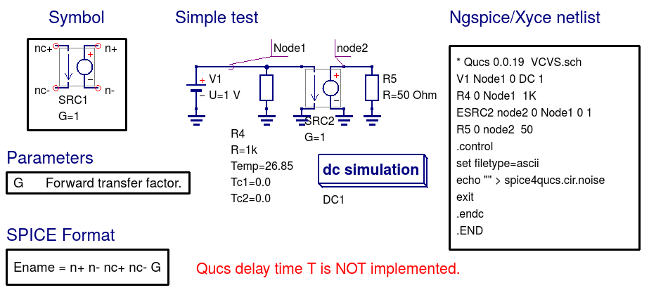
Linear Voltage Controlled Voltage Source (E)
Probes
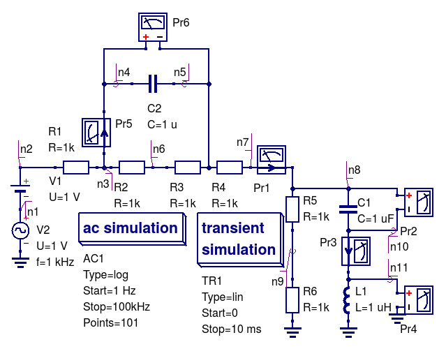
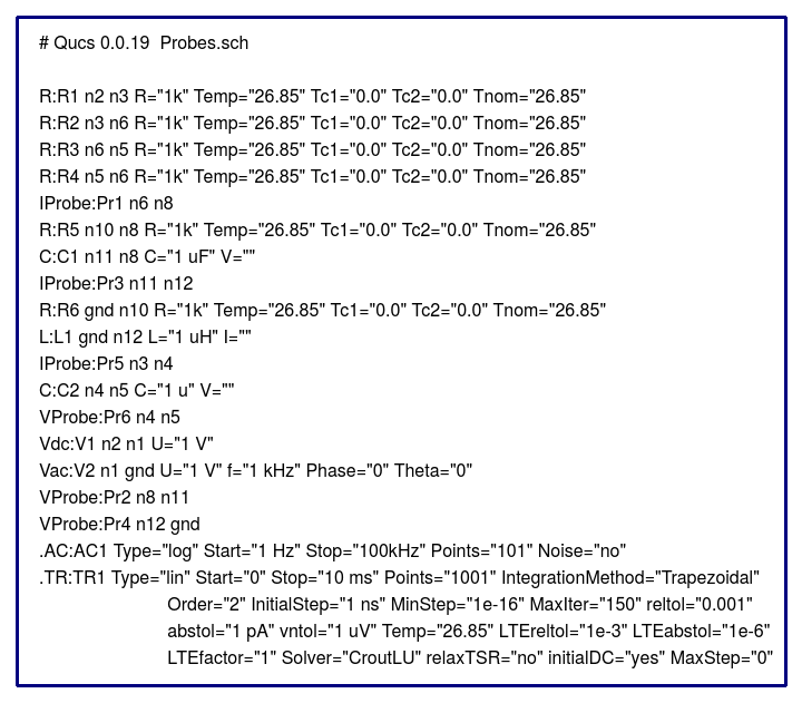
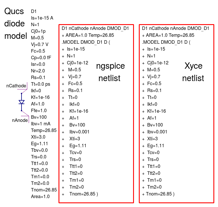
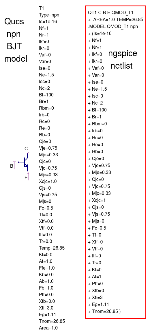
Qucs Netlist
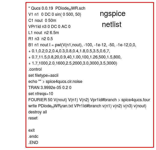
Ngspice Netlist
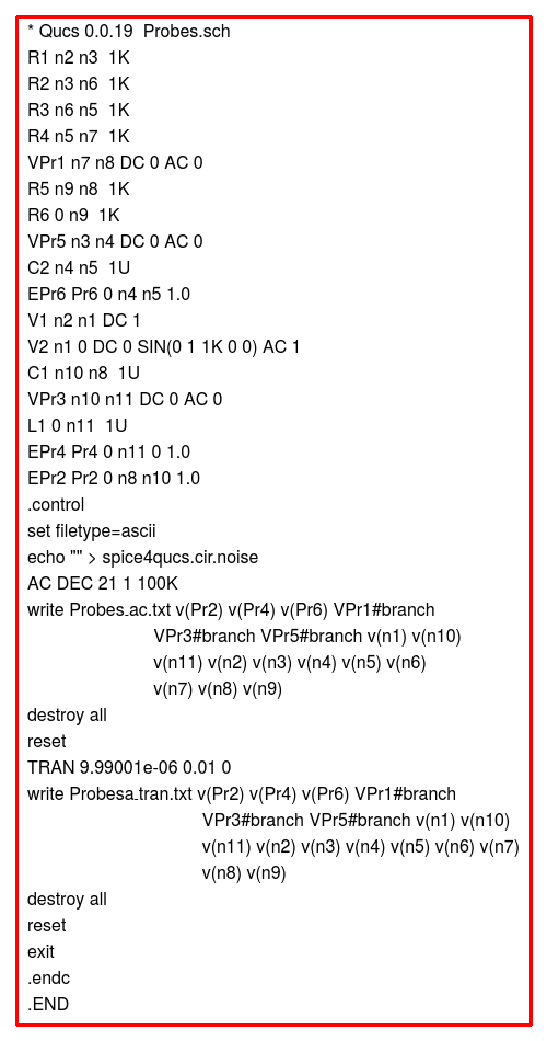
NOTE: To make the Qucs and ngspice netlists readable single lines of width greater than a page width have been indented and continued on one or more lines after the initial entry.
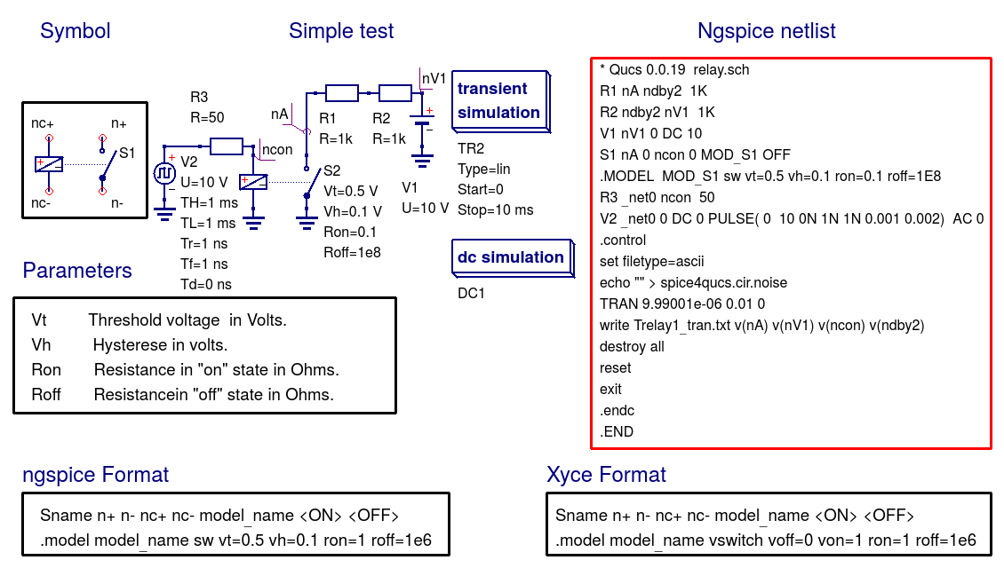
Relay (Voltage controlled switch) (S)
Diode (D)
BJT npn (Qucs T, ngspice Q)
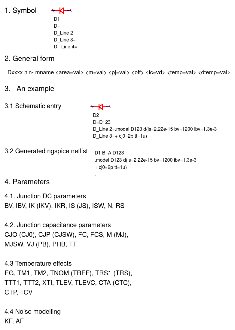
Ngspice diode (D)
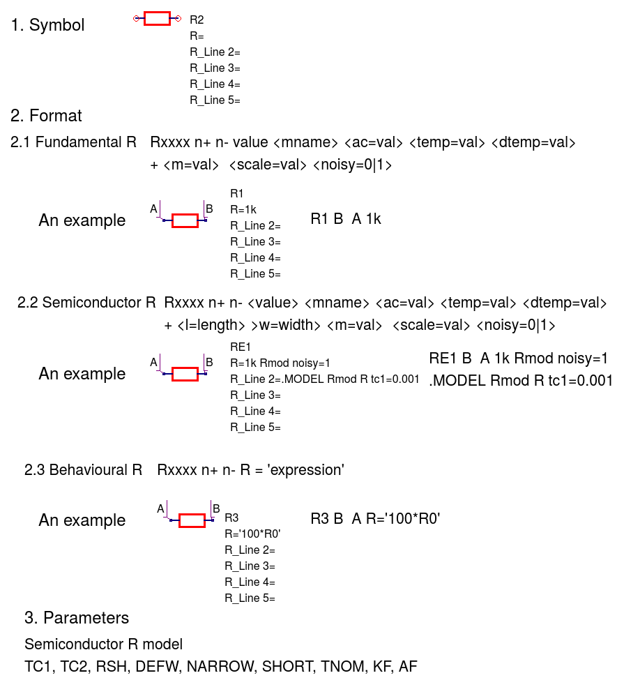
Ngspice resistor (R)
Ngspice capacitor (C)
Ngspice inductor (L)
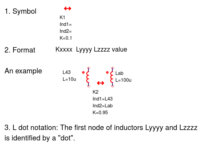
Ngspice mutual inductor (K)
Ngspice independent AC voltage source (V)
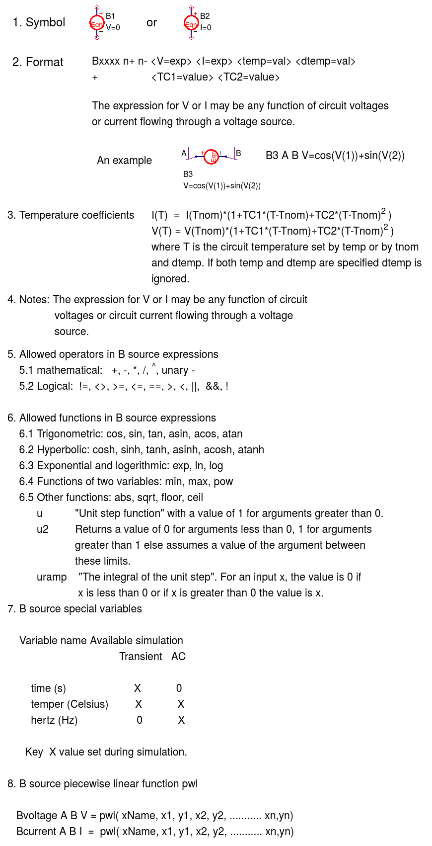
Ngspice non-linear dependent voltage and current sources (B)
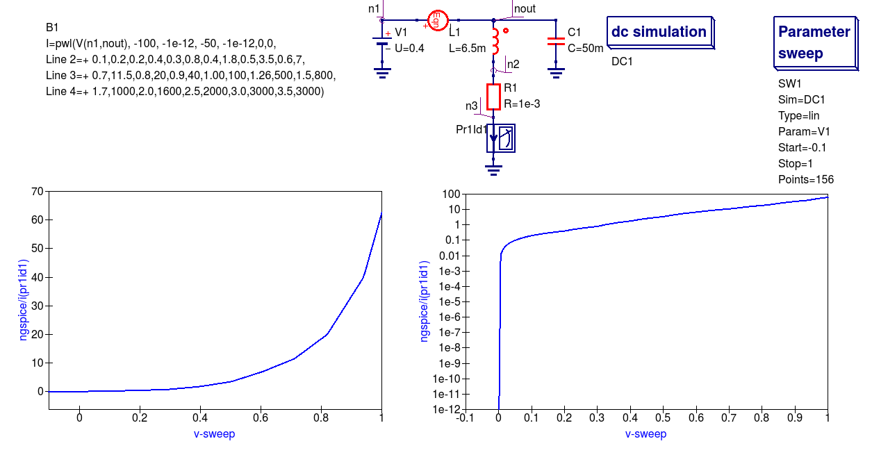
B source example 1: Simulation of the DC characteristics of a diode modelled with a B source pwl function; diode series resistor set at 1e-3 Ohm
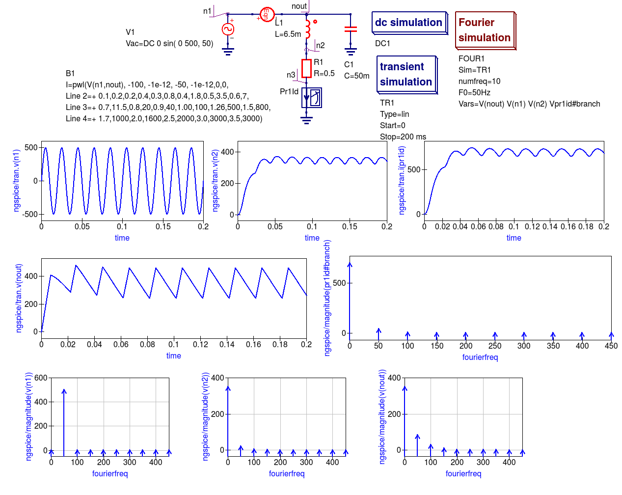
B source example 2: Simulation of the properties of a high power half-wave rectifier circuit with 0.5 Ohm load
6.3 Linear and non-linear transformer models
Qucs release 0.0.18, and earlier versions of the software, includes a number of transformer and coupled inductance models. These models are linear with none of the important non-linear effects found in real transformers, including for example, winding resistance, inductance fringing effects and core saturation. The transformer models introduced in this section inctroduce a number of physical effects which correct the linear transformer limitations. The ideas introduced in their design also act as a set of building blocks which can be used to construct more complex models. The non-linear transformer and core models can be found in the libraries called “Transformers” and “Cores” located in the spice4qucs system library.
Two winding transformer model with in phase primary and secondary voltages and winding resistance
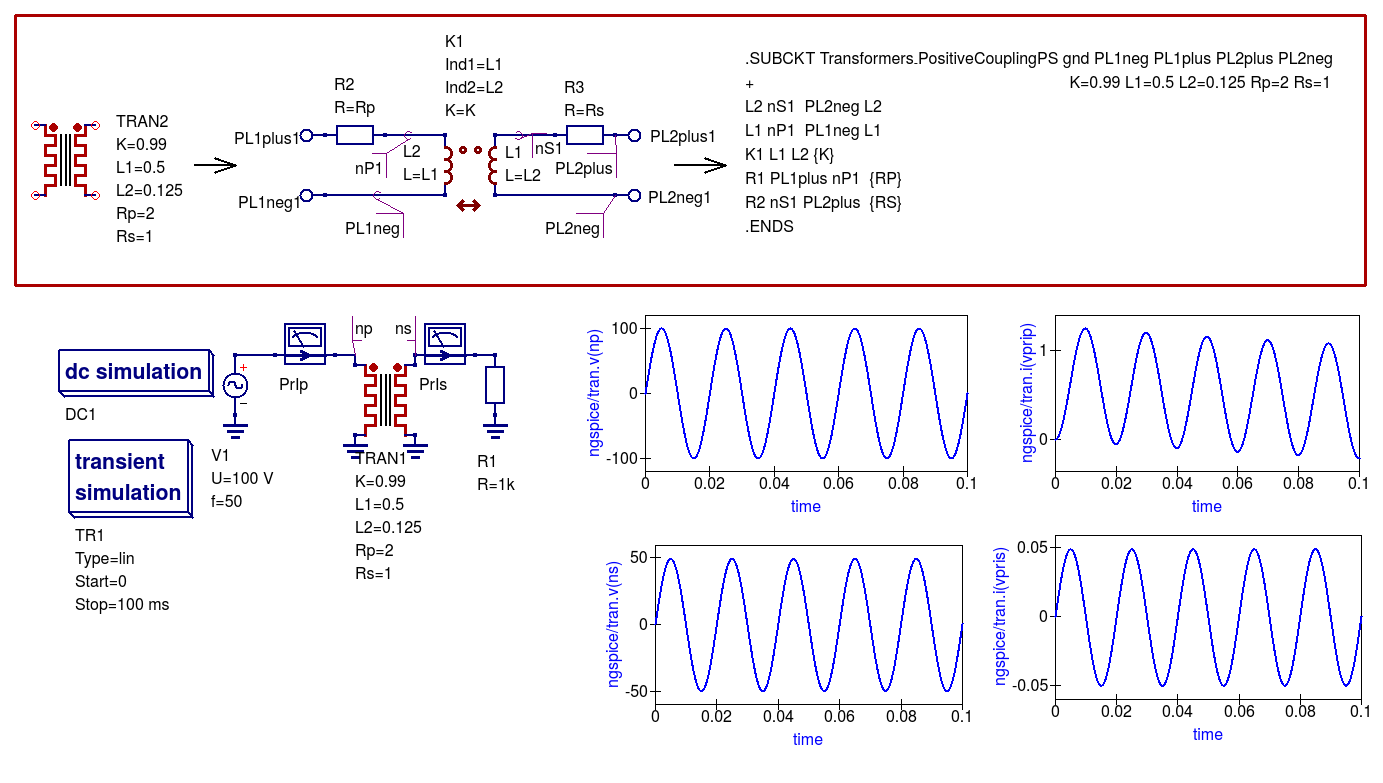 *
*
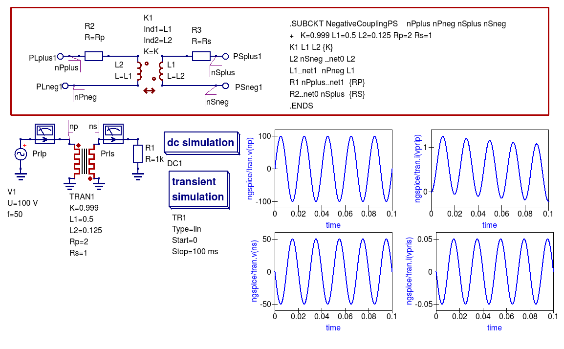
Two winding transformer model with out of phase primary and secondary voltages and winding resistance
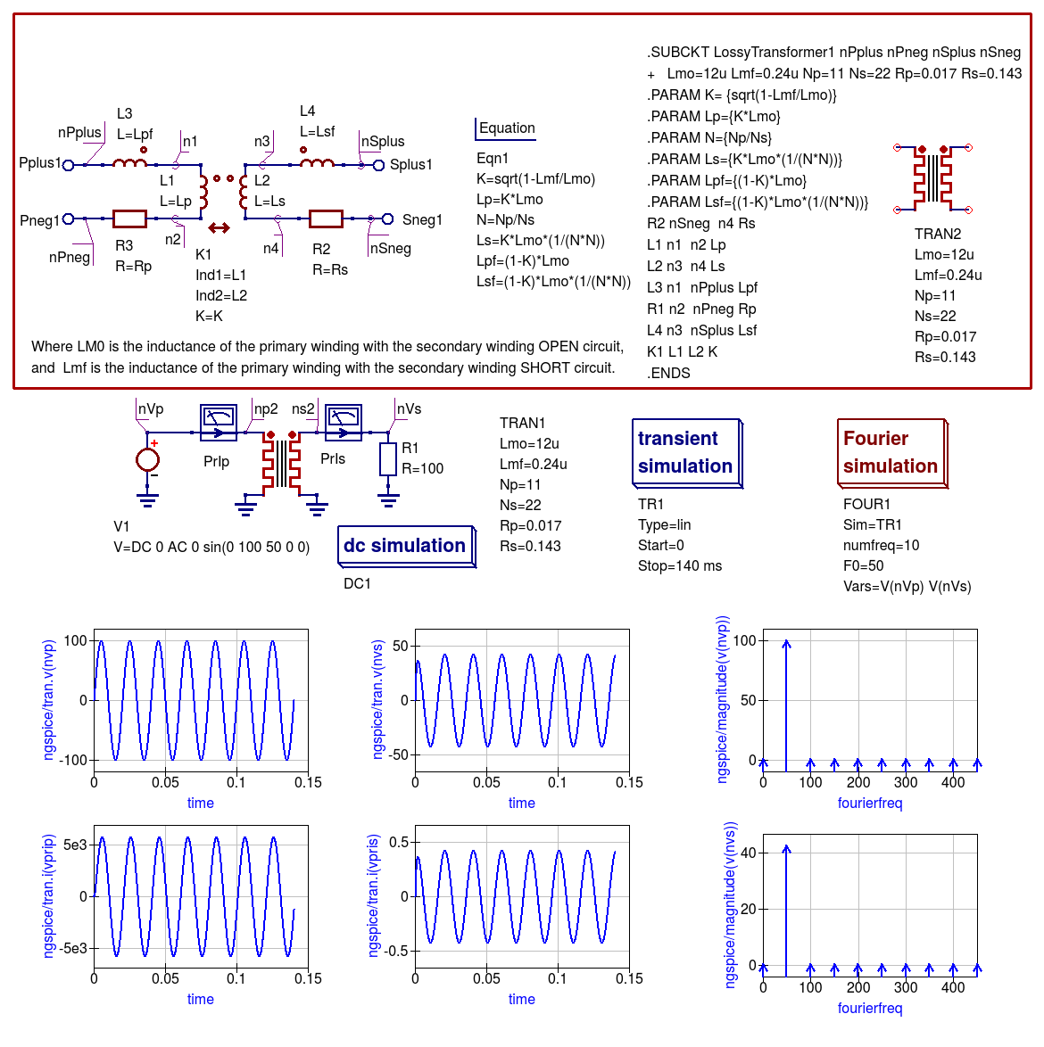
Two winding transformer model with in phase primary and secondary voltages, winding resistance and fringing inductance
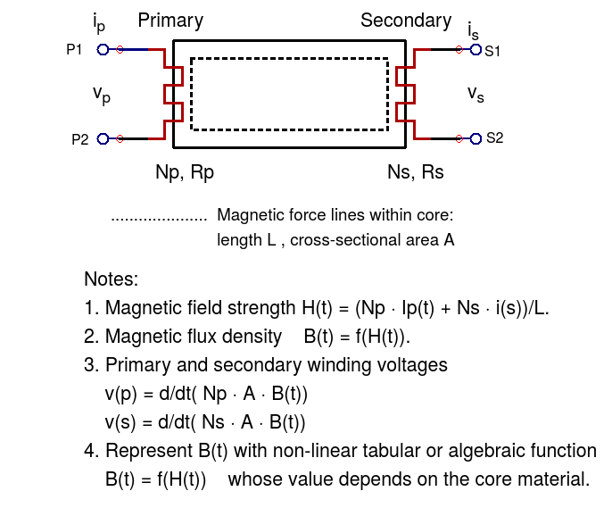
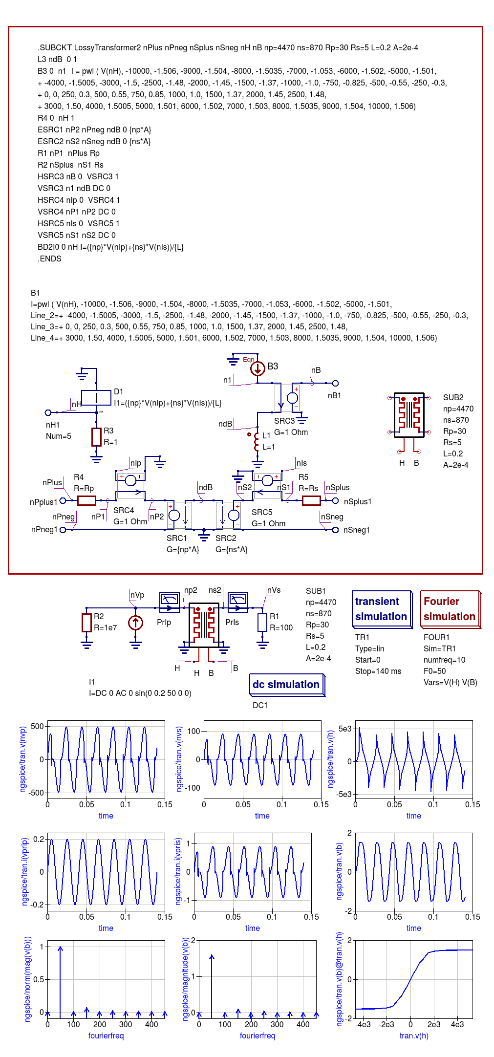
Two winding transformer model with in phase primary and secondary voltages, winding resistance and core saturation
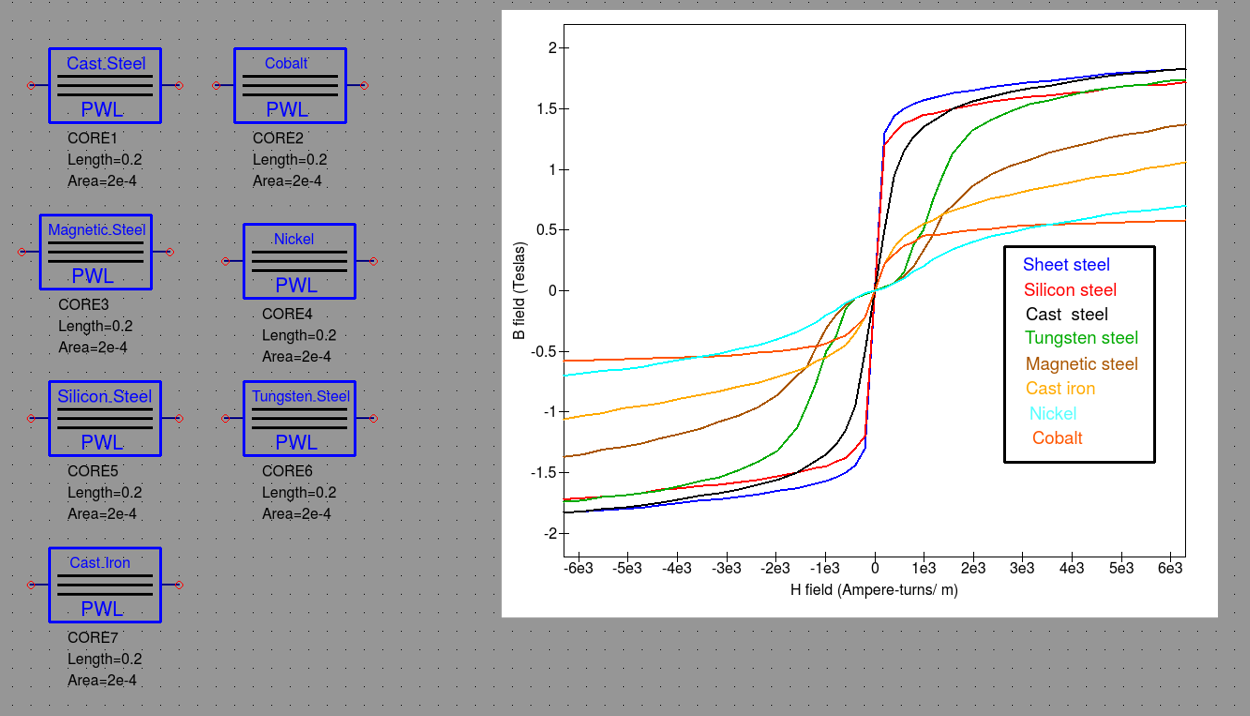
Spice4qucs magnetic core library: symbols and B/H specifications
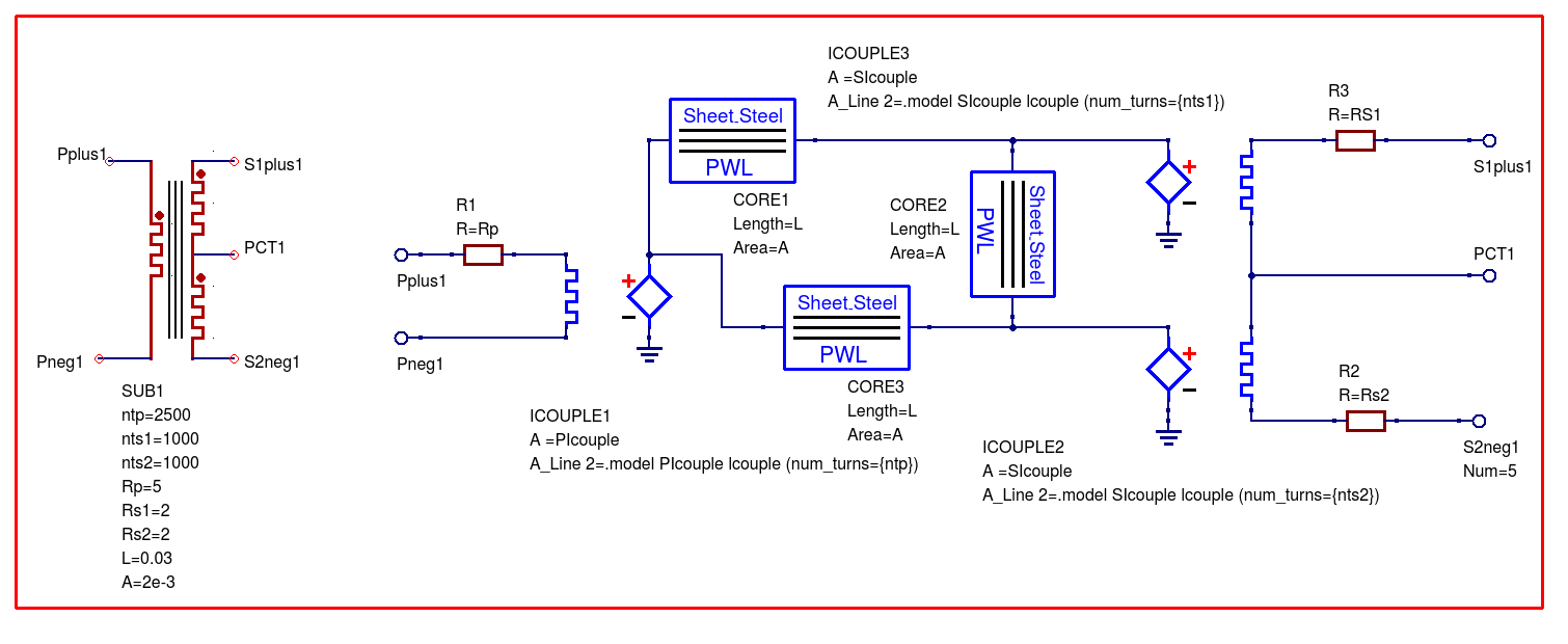
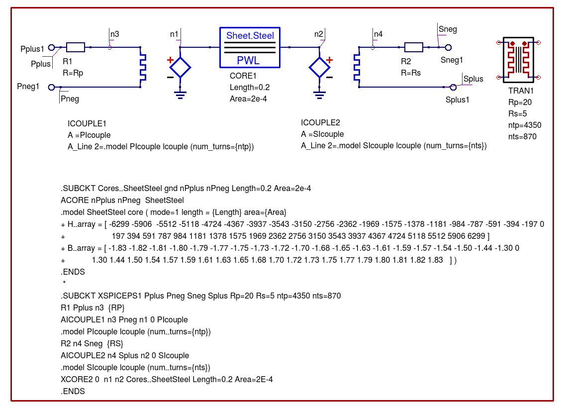
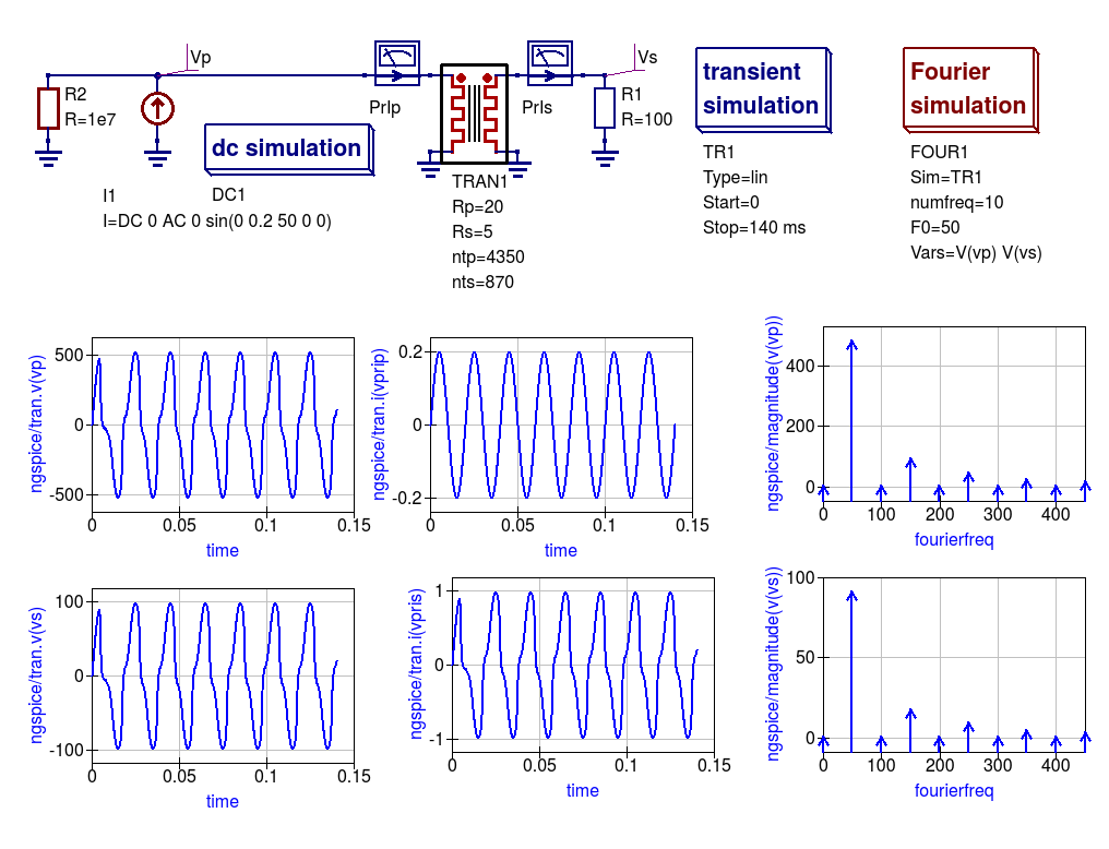
Two winding transformer model with in phase primary and secondary voltages, winding resistance and core saturation (using XSPICE models)
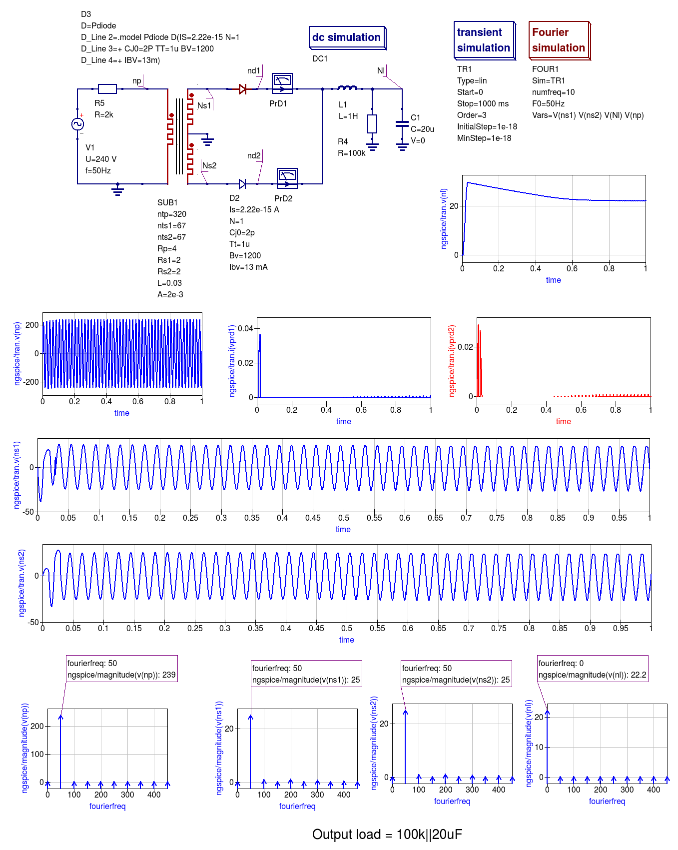
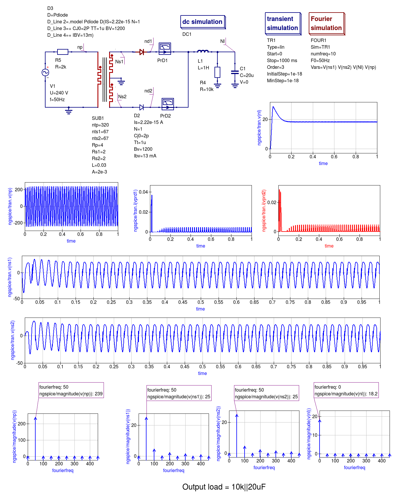
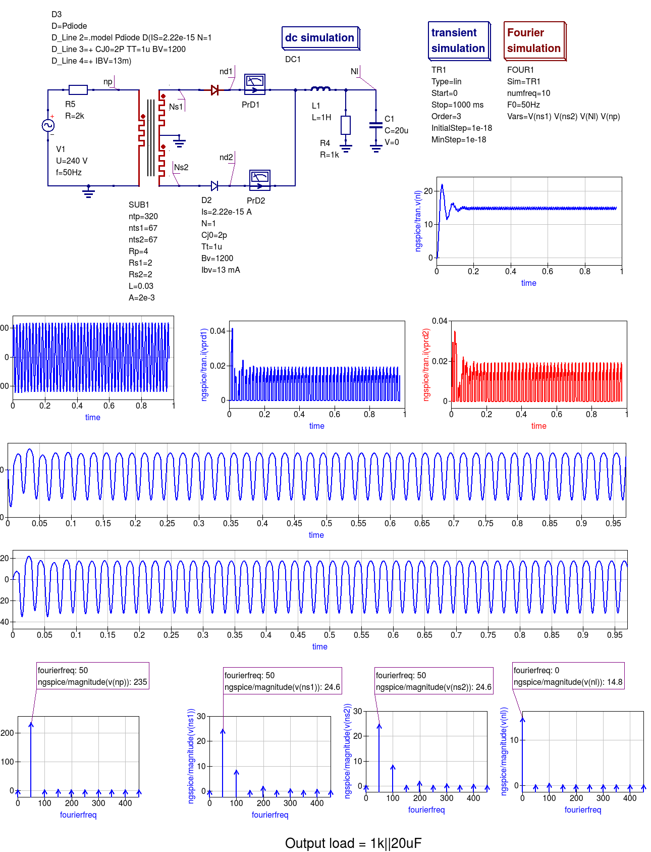
Three winding transformer model with winding resistance and core saturation effects (using XSPICE models): full-wave rectifier example